VRC Documentation
Configuring the Scope
This section describes some of the common functions you can use to control the way your scope looks and how the sector file data is drawn.
Zooming & Panning the Scope
To zoom the scope, use the mousewheel or the F11/F12 keys. Panning the scope can be accomplished by holding down the right mouse button and moving the mouse. You can also instantly recenter the scope by double-right-clicking on a point.
The View Menu
The View Menu is used to toggle the display of various items on the scope. Here's a screenshot:
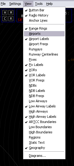
The "Button Bar" option toggles the display of the Button Bar, which is the row of buttons across the very top of the Primary Display.
The "Radio History" option toggles the display of the radio history area at the bottom of the Primary Display.
The "Anchor Lines" option toggles the display of anchor lines on the scope. Refer to the Anchors section of the "Some Useful Tools" page for details on creating anchors.
The next section of the View Menu contains toggles for all the various types of data contained in the sector file, as well as an option to toggle the range rings on and off.
The last item in the View Menu, labelled "Diagrams...", opens a new window which lists all the items from the SIDS and STARS sections of your currently-loaded sector file. Refer to the following section for details.
The Diagrams Window
The Diagrams Window is accessed by choosing "Diagrams..." from the "View" menu or by pressing CTRL+G. Here's a screenshot:
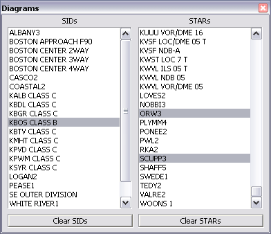
The two lists in this window include the entries from the SIDS and STARS sections of the currently-loaded sector file. (Note that those sections are often used for other types of diagrams such as airspace diagrams, sector split definitions, etc.) To enable or disable the display of any of the listed diagrams, simply click on the entry. Any entries currently being drawn are highlighted in gray. Press the buttons underneath each list to unselect all entries in the associated list.
When you are done making selections from the Diagrams lists, press the Esc key or press the X icon in the upper-right corner to close the window.
Note that each open display has its own Diagrams Window. Selected diagrams are only visible in the associated Display.
Setting Sector Data Colors
All color selections in VRC are made via the color profiles. You can modify the colors in a color profile by choosing "Color Profile->Modify Current..." from the "Settings" menu. Here's a screenshot:
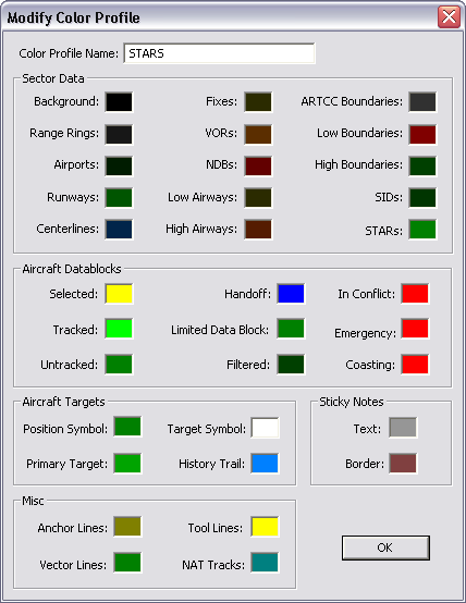
In order to change one of the color settings, simply click on the colored box next to the item you want to change. A standard color selection window will appear. Choose your color and press "OK". The new color will be shown in the box next to the item name. Note that new color assignments take effect immediately, though you obviously won't see the color change unless the color profile is in use on at least one of your scope windows. Changes to color profiles are saved in the INI file once you choose "Save Profile" from the "File" menu.
Most of the color items in this window are self-explanatory, but two of them warrant an explanation. The first is "Anchor Lines". The color you select here will be used when you set an "Anchor" for an aircraft and you have "Anchor Lines" enabled in the "View" menu. See "Some Useful Tools" for more information on Anchors.
The other item that may not be self-explanatory is "Tool Lines". This color is used for several different functions within VRC that draw lines on the scope. They include the "Ruler Line", the "Separation Predictor Lines", and the "Route Line". See "Some Useful Tools" for more information on these functions. The Tool Line color is also used when highlighting a fix using the .find command or when showing your visibility center(s).
Scope Configuration Commands
Following are some of the more important and most commonly-used commands for working with the scope:
- .rings POINT
- Centers the range rings on the specified POINT. (VOR, Airport, Intersection, etc.)
- .norings
- Disables range rings
- .center POINT
- Centers the scope on the specified POINT.
- .vis POINT
- Sets your primary visibility center at the specified POINT.
- .vis2/.vis3/.vis4 POINT
- Sets one of your secondary visibility centers at the specified POINT.
- .novis
- Clears all visibility centers. The center point of the scope will then be your visibility center.
- .showvis
- Shows a circle around any configured visibility centers.
- .ff FIX ...
- Toggles the display of one or more individual intersections.
- .fv VOR ...
- Toggles the display of one or more individual VORs.
- .fn NDB ...
- Toggles the display of one or more individual NDBs.
- .fa AIRPORT ...
- Toggles the display of one or more individual Airports.
- .fc RUNWAY ...
- Toggles the display of one or more individual runway centerlines.
- .fw AIRWAY ...
- Toggles the display of one or more individual airways.
- .fd Diagram Name|Diagram Name|Diagram Name|...
- Toggles the display of one or more diagrams (SIDs/STARs).
- .nofixes
- Disables the display of fixes toggled on via the .ff command.
- .novors
- Disables the display of VORs toggled on via the .fv command.
- .nondbs
- Disables the display of NDBs toggled on via the .fn command.
- .noairports
- Disables the display of airports toggled on via the .fa command.
- .nocenterlines
- Disables the display of runway centerlines toggled on via the .fc command.
- .noairways
- Disables the display of airways toggled on via the .fw command.
- .nodiagrams
- Disables the display of all diagrams toggled on via the .fd command.
Visibility Center(s)
As mentioned above, you can use the .vis/.vis2/.vis3/.vis4 commands to define the "Visibility Center(s)" for your scopes. A visibility center determines the center point of your sector. Combined with your visibility range, the visibility center is used by the network to determine which aircraft are visibile on your scope. For example, if you issue the following command:
.vis KBOS
Then your primary visibility center will be set at the Boston airport. If your visibility range is set to 100 NM, then you will be able to see targets within 100 NM of KBOS, regardless of where your scope is actually centered. If your scope was centered on the Syracuse VOR (SYR) which is about 250 miles west of KBOS, you would still only see aircraft around KBOS ... you would not see aircraft near SYR.
In some cases, a single center point isn't enough to cover a very large or oddly-shaped sector. If this applies to your sector (generally this only happens in Oceanic sectors) then you can define additional (secondary) visibility centers. You can specify 3 secondary visibility centers, for a total of four. Your visibility range applies separately to each visibility center. For example, in addition to the .vis command issued in the example above, if you entered:
.vis2 SYR
Then you would still see aircraft within 100 NM of KBOS, but you would also see aircraft within 100 NM of the Syracuse VOR. The secondary visibility centers allow you to expand the range of your radar in order to cover extremely large or strangely-shaped sectors. Please use them with caution, and only when absolutely necessary, since each time you define an additional visibility center, you consume additional network bandwidth. For example, a controller with three visibility centers defined consumes three times as much bandwidth as a controller with just the primary visibility defined, assuming they both have the same visibility range.
Note that your visibility center(s) also determine which other controllers you will see in your Controller List.
You can change (update) a visibility center at any time simply by re-issuing the command with a new point. If you wish to clear your visibility centers and revert to having only one, issue the .novis command. If you have no visbility centers defined, then the center of your scope becomes the visibility center. This of course means that your visibility center moves as you pan the scope. This is why it's always a good idea to set your primary visibility center (using .vis) as soon as you open a profile and/or load a new sector file. (Loading a new sector file clears any defined visibility centers.)
Airspace Filters
In VRC, your airspace filters are defined simply by a floor and a ceiling. If you define this floor and/or ceiling, and your airspace filters are active, then targets above your ceiling or below your floor will be shown using the "Filtered" color. Some controllers like to set the filtered color to something quite dark, so that the targets can be seen, but they are not distracting and so that they are not easily mistaken for aircraft within the defined airspace.
You also have the option of hiding the data block and/or target symbol for filtered aircraft. (See "Configuring VRC.")
Starting with VRC 1.2, you can define airspace filters separately for each scope. To set the filters, press Ctrl-Alt-F and set the appropriate values in the resulting popup window. You can also choose "Filters->Configure..." from the "Settings" menu.
You can also define a hard radar floor for each scope. The radar floor is different from the airspace floor in that aircraft below the radar floor will never be displayed, regardless of your filter settings. This is to allow you to simulate line-of-sight radar coverage in hilly or mountainous areas.
To enable or disable the airspace filters, press Ctrl-F, or choose "Filters->Enable..." from the "Settings" menu. On the primary scope, you can also click the Filters button in the button bar to toggle the filters on and off for the primary scope. Note that the radar floor setting is always in effect, whether your airspace floor and ceiling are enabled or not.
The Button Bar
As mentioned above, you can turn the Button Bar on and off using the "View" menu. You can also select individual types of buttons using the "General..." option in the "Settings" menu. For example, if you are working Ground, you might not have any need for the Timer button, which is normally used for wake turbulence separation by Tower. In that case, you might disable the Timer button using the checkbox in the General Settings.
Saving Your Configurations
Remember to always save your configurations in a profile for easy recall the next time you work the same position!